Projects2026
Foldable Electric Dirtbike
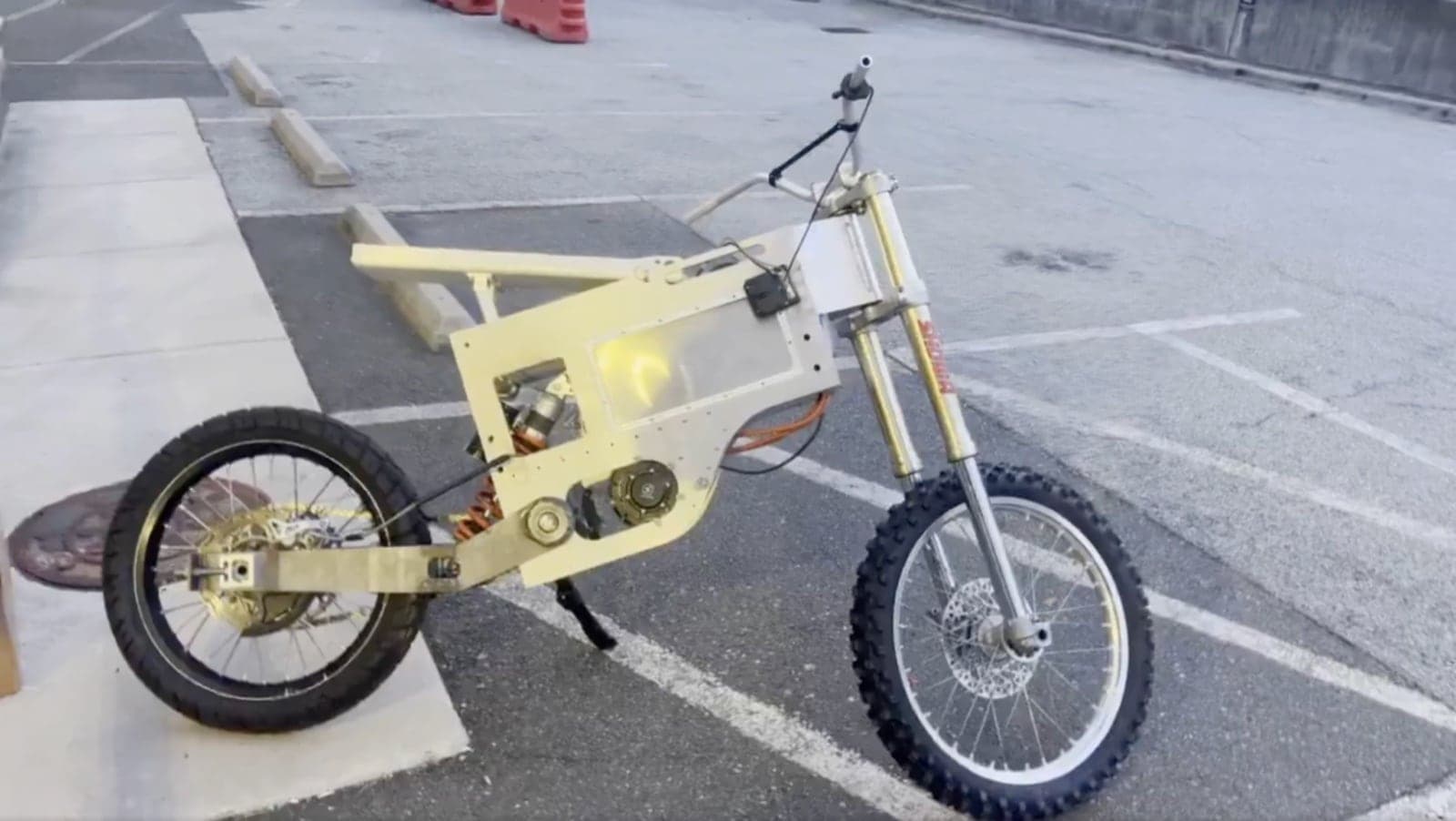
A foldable electric dirt bike built from flat aluminum plate. I designed and wired the electrical system and helped weld the 74V pack.
- Year
- 2026
- Role
- Electrical system and battery pack
- Duration
- 3 months (Feb–Apr 2026)
- Team
- With Marco Schönert
- Context
- Personal project
- KiCad
- 20s12p P42A 21700 pack
- Nucular P24F controller
- QS138 90H motor
- 72V to 12V DC-DC
- Spot welding
- CAD
TL;DR
A foldable electric dirt bike I built with my friend Marco Schönert over about three months. I worked on the electrical system: I split it into four subsystems, drew each as its own KiCad harness, merged them into one schematic, and wired the bike from it. I also worked on spot-welding the pack, a custom 20s12p battery of P42A 21700 cells: 74V nominal, about 3.7 kWh.
Why I built it
We wanted a light, capable electric dirt bike designed around manufacturability rather than tradition. The frame is flat aluminum plate instead of tubing, so anyone with a CNC mill, a TIG welder and a press brake (or a SendCutSend order) could replicate it.
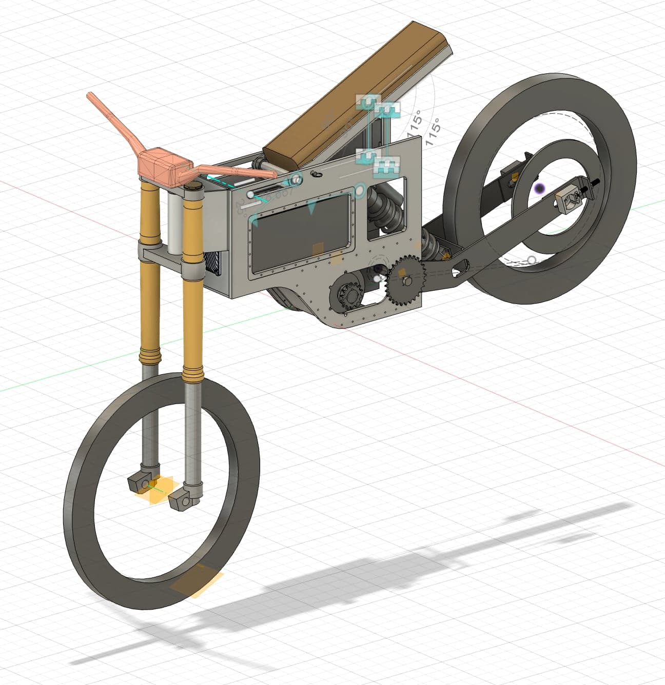
It folds so that it fits in an elevator. It also looks cool, a bit like the bike from the movie Oblivion. The fold drove the rest of the design: the rear wheel pivots about the swingarm pivot, and that forced the jackshaft drivetrain described below.
How it works
Sizing the battery
The series count was set by the controller. The Nucular P24F has a 92V limit, and 22 cells in series peak at 92.4V, too close to that limit. 21s didn't divide cleanly into the pack geometry. 20s gives 74V nominal and 84V at full charge.
The parallel count came from current. A 20 kW peak at 84V is about 238A. We derated each P42A to half its 45A rating, 22.5A per cell, which needs between 10 and 11 cells in parallel. We rounded up to 12p, the nearest count that suited the layout.
We chose the P42A because it's cheap and widely available, cheaper than the P45B, and the 21700 format holds more than an 18650.
Building the pack
The pack is two 10s12p modules stacked and joined in series. Parallel groups are spot-welded with two layers of 8 × 0.15 mm nickel strip. Series links are laser-cut 0.25 mm copper, because each link carries about 25A. A copper bus of about 9 mm² joins the two modules. The cover is 3D-printed in two parts, and the BMS is a 20s unit rated 150A continuous and 300A peak.
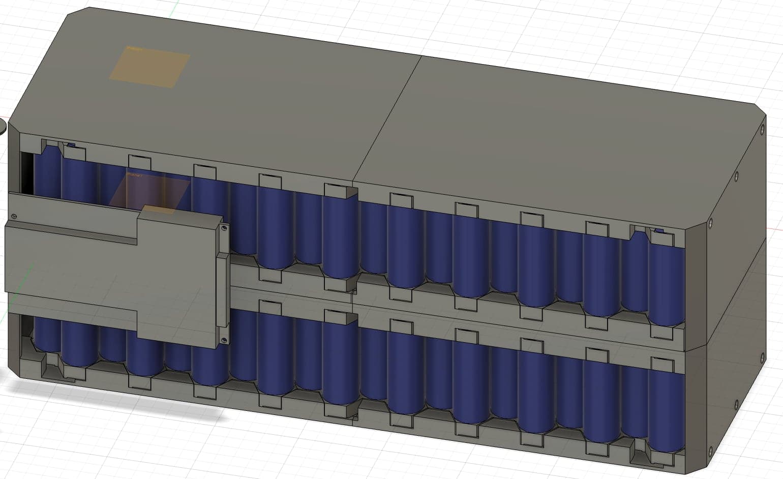
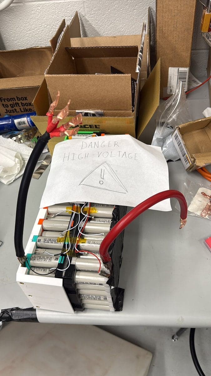
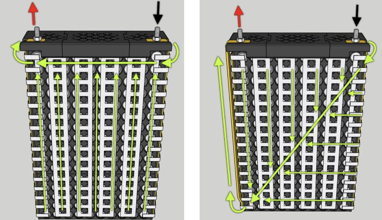
We routed the current path so the lowest-resistance route runs through most of the cells, which keeps the cells draining evenly. With both terminals on the same end, the cells nearest them get used quicker. Taking the path diagonally across the pack evens that out.
Four harnesses, one schematic
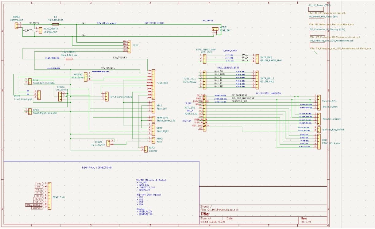
I split the electrical system into four subsystems and drew each one as its own KiCad harness:
- High-voltage distribution. Pack, main fuse, HV bus, then the P24F controller and the 72V to 12V DC-DC converter.
- Motor phase and Hall feedback between the P24F and the QS138.
- The controller's low-voltage I/O. Key switch, throttle, regen brake, the four auxiliary inputs, and the Nucular display.
- The 12V accessory system. Fuse box, lights, indicators, horn, and the brake-light switch, with its own main fuse.
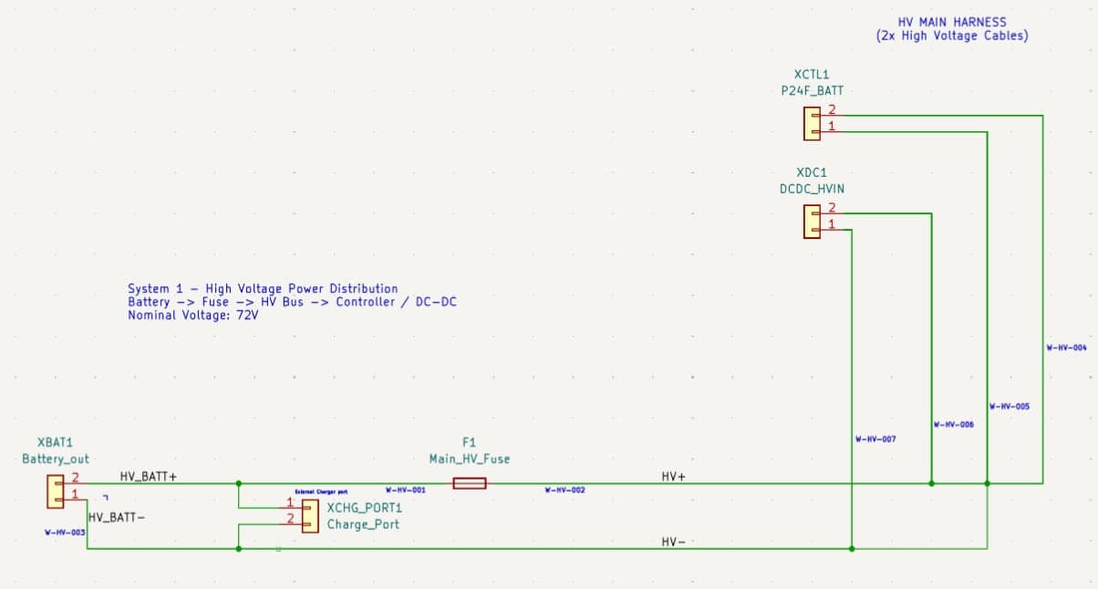
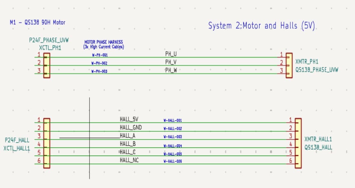
Then I merged them into one top-level schematic and wired the bike from it.
Drivetrain
Power runs through the P24F into a QS138 motor and reaches the rear wheel through a two-stage reduction: 14T to 28T is 2:1, and 14T to 49T is 3.5:1, for 7:1 overall. We targeted 7:1 because acceleration matters more than top speed on a dirt bike. It gives about 453 Nm at the wheel by our spreadsheet.
The sprockets are custom 4130 chromoly, milled from quarter-inch plate. The two jackshaft sprockets sit as close together as possible to minimize bending on the 1" chromoly shaft and the load on its bearings. The chain is plain 520 with no O-rings, which is easier to clean off-road.
Frame
The frame is two parallel 6061 aluminum plates joined by bent, welded 5052 sheet metal, with a five-blade chromoly steel swingarm fabricated on a custom jig.
The numbers, and which are real
The acceleration and weight figures are estimates, not measurements. Our spreadsheet puts 0–100 km/h at under 4 seconds, at roughly 70 kg for the bike alone.
Key decisions
A jackshaft on the pivot axis
When the bike folds, the rear wheel swings about the swingarm pivot, and a direct chain would change length through that arc. Putting a jackshaft exactly on the pivot axis keeps both center distances fixed: motor to jackshaft, and jackshaft to wheel. The same geometry also removes chain growth through suspension travel.
instead ofA chain running straight from the motor to the wheel
Two stages to reach 7:1
Splitting the reduction into 2:1 and 3.5:1 gets to 7:1 with sprockets of a sensible size.
instead ofOne enormous rear sprocket
20 cells in series
The P24F's limit is 92V. 20s tops out at 84V and leaves real margin.
instead of22s, which peaks at 92.4V, and 21s, which didn't fit the pack geometry
Run each cell at half its rating
Derating the P42A from 45A to 22.5A per cell is what set 12p.
instead ofFewer cells in parallel, each pushed harder
Flat plate, not tubing
Anyone with a CNC mill, a TIG welder and a press brake, or a SendCutSend order, can replicate a plate frame.
instead ofA traditional tube frame
What went wrong
Once everything was wired up, getting the display to fire up from the battery pack took several attempts, and each cause was small.
- The BMS was wired wrong. We bought it cheaply off Alibaba, so we were never sure how good it would be.
- Resistance in the circuit was too low when we connected the pack, so there were pretty big sparks. It is a very big battery, after all.
- Thick wire is annoying to work with.
The other thing that needed care was managing the voltage each component saw, so we didn't fry anything: 84V at the pack, 12V for the accessories, 5V for the Hall sensors and throttle.